Arduino Uno R3: Assign Push Button to Digital Input Pin

Learn how to code and assign pushbutton to light up LED.

Materials Needed

  1. Arduino Uno R3 with cable.
  2. 1x Breadboard Solderless.
  3. 1x LED.
  4. 1x Pushbutton.
  5. 1x 1K resistor.
  6. 4x Jumper.

Step 1

Connect a pushbutton in the middle of the board Connect a jumper to the board beside pushbutton and to Digital Input Pin A0 Connect 1K resistor to the board beside jumper and to negative board input Connect a jumper to the negative board align with resistor and to GND

Step 2

Connect a jumper to the board and to beside pushbutton Connect a jumper to the board and to pin number 2

Step 3

Connect LED to board between two jumpers while positive side connected to jumper pin number 2 and negative side connected to jumper pushbutton

Simple Programming Example

Basic code to Assign Push Button to Digital Input Pin:

//LearnIoT Academy
//Assign Pushbutton LED with Serial Monitor
int ledPin = 2;    // choose the pin for the LED

int buttonValue = 0;

void setup()
{
  Serial.begin(9600);       //To setup Serial Monitor with 9600 baud output
  pinMode(ledPin, OUTPUT);  // declare LED as output
}

void loop()
{

  int buttonValue = analogRead(A0);  //Read in the button value
  Serial.println(buttonValue);    //To check if button was pressed

  if (buttonValue == HIGH) // check if the input is HIGH    
    digitalWrite(ledPin, LOW);  // turn LED OFF
  else
    digitalWrite(ledPin, HIGH );  // turn LED ON
}
            
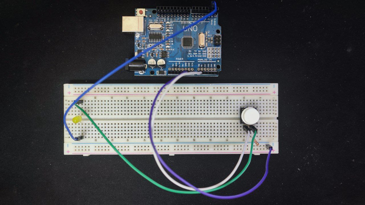
Below is a reference image for the wiring of the assign pushbutton:
learn

Summary

The Serial Monitor will show output of “0” everytime the button is not being push and “600” above everytime it was pushed.
The LED that light up after being pushed.